I don't include many class projects from undergraduate courses on this site because typically they aren't very interesting or don't have much technical substance. However, this project probably taught me the most about programming of any I've done. Unfortunately, because it is a class project I'm unable to share the code publicly, however if you are interested shoot me an email I will provide access.
As a part of my advanced embedded systems course I spent the semester building a working digital oscilloscope on this Nexys FPGA board. The project was written entirely in VHDL with a little bit of C code for software control.
Drawing the Screen
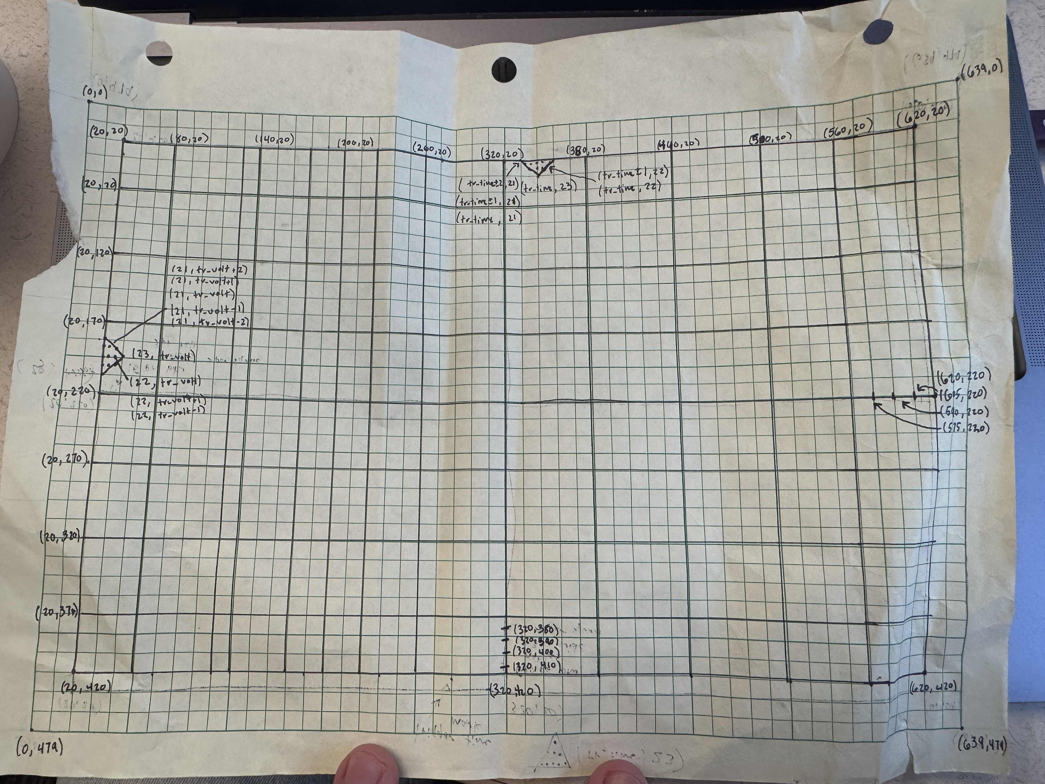
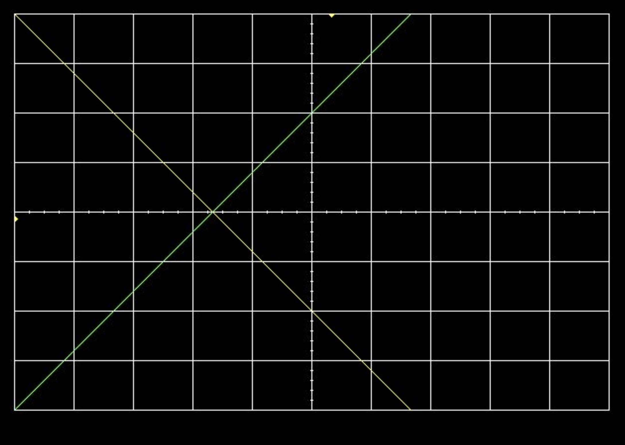
I started by writing a VGA controller that, when paired with the VGA-HDMI module, draws the oscilloscope “scopeface”: a white grid, two trigger markers, and placeholder channel lines (pictured below). I was tasked with drawing out the grid and coordinates on paper as a tedious class assignment, although it ended up relieving a lot of headache when drawing the pixels on screen.
To get pixels to display, the module has horizontal (h) and vertical (v) counters that track the current pixels coordinates across the grid. To get anything to display, these counters have to be synced perfectly corresponding to the clock speed and refresh rate of the display. The image below shows the calculated result of those counts for 60hz display, and the waveform diagram used to confirm those counts matched the calculated results.
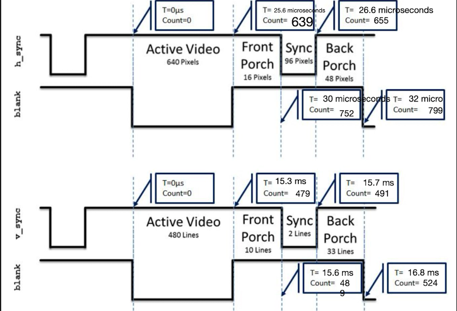
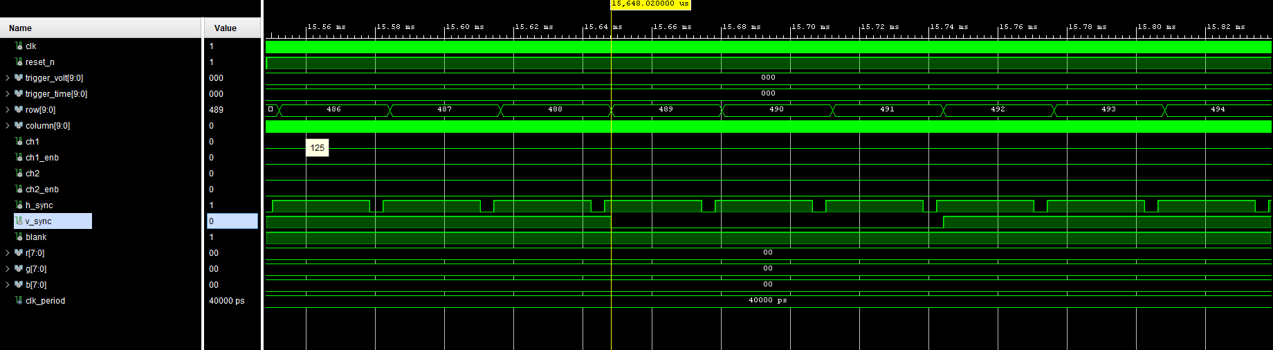
A fun early bug: my V counter didn’t tick right after H rolled over. The fix was to drive the roll signal asynchronously (outside the process), so V increments on the same cycle and HDMI actually lights up. I grained a lot more respect for my computer seamlessly projecting to my external monitor after working on this bug.
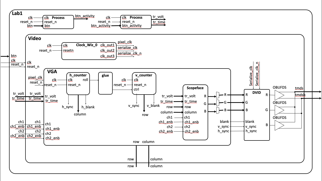
Here is a closer look at the software diagram for this module, since it's abstracted in the main diagram.
Making a real oscilloscope
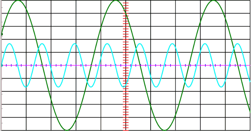
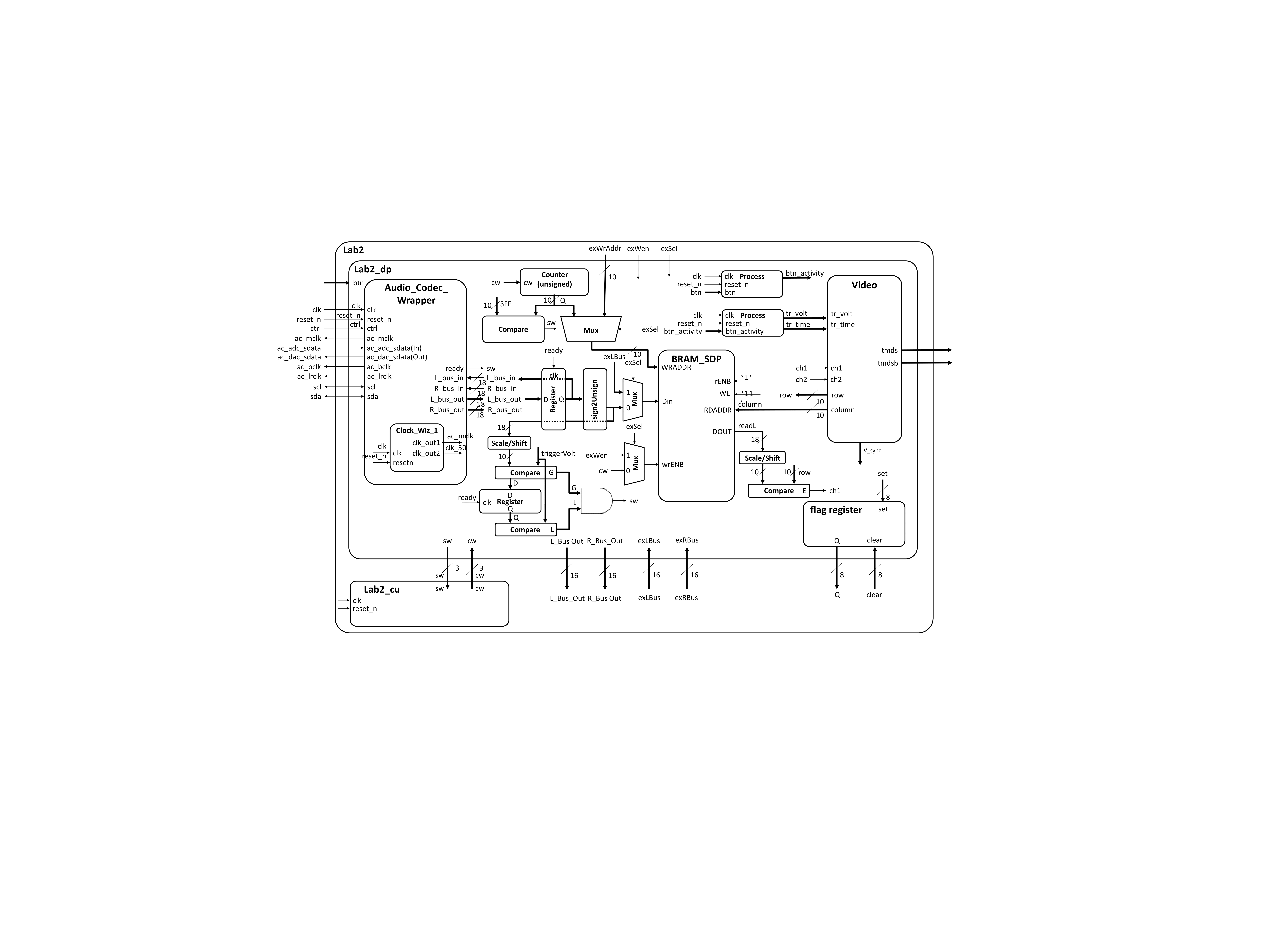
Next I integrated the Nexys Video audio codec so the screen shows real left/right audio channels instead of diagonals. To do this, dual BRAM memories have to be added that store the voltages coming in from the codec. The BRAM is simultaneously read and converted into pixel positions to display a point on the wave on the screen through the video module.
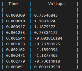
This is an example of what an input from the codec would look like
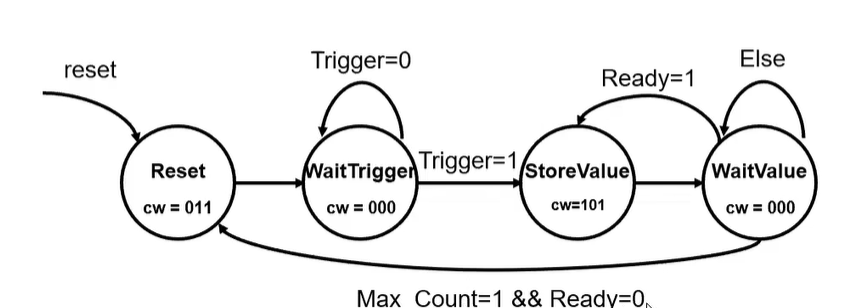
I added dual BRAM, each stores the samples from the left and right input. I also implemented a write-address counter (20 → 1023) so the samples are written to the correct spot in memory, and are written over only have ~1000 clock cycles. Finally there is a small control unit (finite state machine) to move samples reliably, so we aren't writing samples to the same address.
There is a lot of logic performed on the codec samples before the data is put into BRAM. Essentially just scaling and shifting the values, but if you're curious reference the hardware diagram at the top.
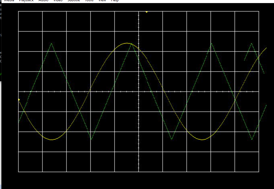
The biggest fixes here were about signed → unsigned conversion and scaling for the display. Once the left channel looked right, I duplicated the logic for the right channel, added a simple flag register for later, and got both channels drawing cleanly.
Software Control
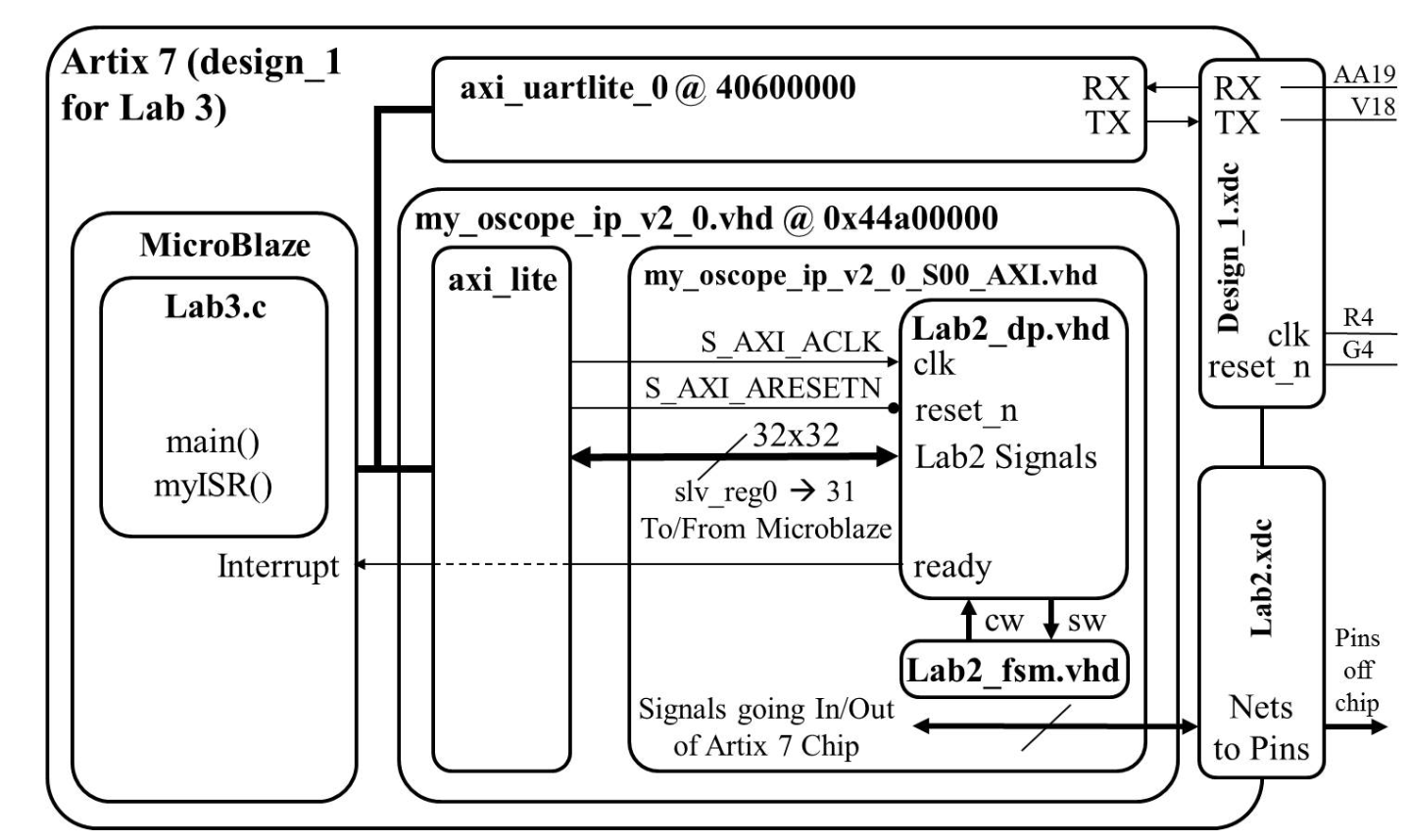
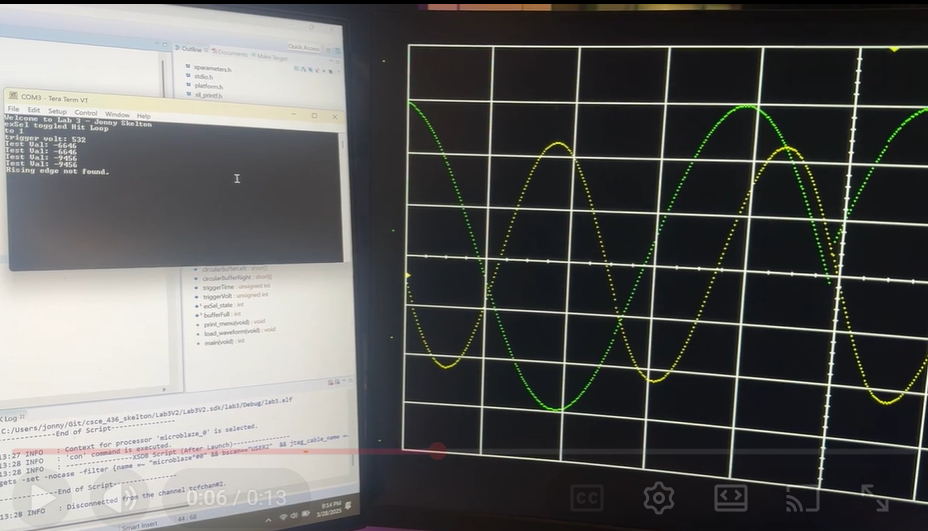
The motivation of adding software control is to change the trigger volt and trigger time I packaged the oscilloscope datapath as custom IP, dropped it into a MicroBlaze system, and wrote C to control it. Beyond tweaking Trigger Volt and Trigger Time, I can toggle channel visibility, and use an interrupt to pull samples into circular buffers. I also added an “align on rising edge” mode that offsets the display to a trigger point.
Function Generator
To round things out, I implemented a function generator using direct digital synthesis. I pre-initialized two BRAMs with 1024-sample sine and triangle tables, added middleware to scale amplitude and step phase, and streamed them through the audio codec. Buttons toggle waveform, amplitude, and frequency.
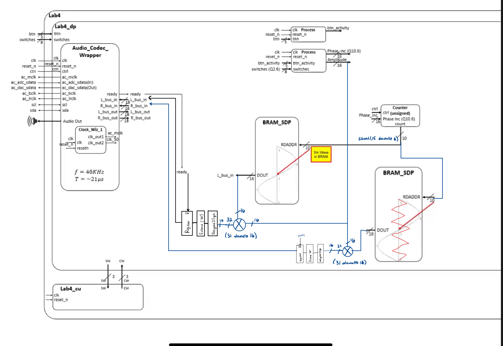
I ran into a bug where my counter was incrementing off the ready signal because I hadn’t wired the active-low reset correctly. Adding reset <= not reset_n fixed it immediately, but didn't feel too smart for not paying attention to the low vs. high reset.
Demos
- Lab 2 — audio channels drawing on the scopeface: https://youtu.be/0kF7cVMXa0M
- Lab 3 — software control and buffering: https://youtu.be/ofrfKFrAkjk, https://youtu.be/migLPM9MalYG
- Lab 4 — function generator (waveform toggle, amplitude & frequency): https://youtu.be/2DZNn7cejGI